 EN
EN

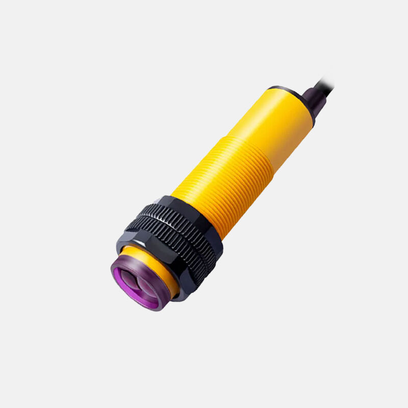
In modern industrial automation, the ability to detect objects accurately over varying distances is a fundamental requirement. A photoelectric sensor switch addresses this need by using light-based detection principles that allow it to sense targets without physical contact. Unlike mechanical switches that require direct touch, a photoelectric sensor switch emits a beam of light and measures changes in that beam caused by the presence or absence of an object. This core mechanism is what makes it inherently capable of operating across a wide range of distances, from a few millimeters to tens of meters depending on the configuration and technology used.
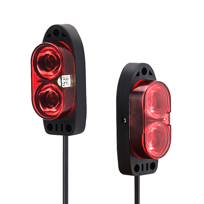
Understanding how a photoelectric sensor switch improves detection range requires looking at the interplay between optical design, signal processing, and operating mode. Each of these factors contributes to how far and how reliably the sensor can detect a target. Engineers and procurement specialists selecting sensors for production lines, packaging systems, or logistics equipment need to understand these mechanisms in order to match the right sensor to the right application. This article breaks down the key technical and design factors that allow a photoelectric sensor switch to extend and optimize its detection range in real-world industrial environments.
The Optical Principles Behind Extended Detection Range
How Light Emission Technology Affects Range
The light source used in a photoelectric sensor switch is one of the most direct determinants of its detection range. Most modern units use infrared LEDs or visible red laser diodes as their emitters. Infrared LEDs offer a broad emission angle and are cost-effective, making them suitable for short to medium-range applications. Laser-based emitters, by contrast, produce a highly collimated beam with minimal divergence, which allows the light energy to remain concentrated over much longer distances. This focused beam is why laser-type photoelectric sensor switches can achieve detection ranges that far exceed those of standard LED-based models.
The wavelength of the emitted light also plays a role. Infrared wavelengths are less susceptible to interference from ambient visible light, which helps maintain signal integrity at longer distances. Some photoelectric sensor switch designs incorporate modulated light signals, where the emitter pulses at a specific frequency. The receiver is then tuned to detect only that frequency, effectively filtering out background light noise. This modulation technique is a key reason why modern sensors can maintain reliable detection even in brightly lit factory environments where ambient light would otherwise degrade performance.
Optical lens design further amplifies the range capability of a photoelectric sensor switch. Precision-ground lenses focus the emitted beam into a tighter spot and concentrate incoming reflected light onto the receiver element. The quality and geometry of these lenses directly influence how much usable light energy reaches the receiver at a given distance. Higher-quality optics reduce signal loss over distance, which translates directly into a longer effective detection range without sacrificing switching reliability.
Receiver Sensitivity and Signal Processing
The receiver side of a photoelectric sensor switch is equally important to detection range as the emitter. A highly sensitive photodetector can register weaker light signals, which means it can still trigger a reliable output even when the target is far away or when the reflected signal is attenuated by surface characteristics. Avalanche photodiodes and PIN photodiodes are commonly used in high-performance sensors because of their superior sensitivity compared to standard phototransistors.
Signal processing circuitry within the photoelectric sensor switch amplifies and conditions the received signal before making a switching decision. Advanced analog front-end circuits can distinguish between a genuine detection signal and noise, even when the signal-to-noise ratio is low. Digital signal processing techniques, including threshold adjustment and hysteresis control, allow the sensor to maintain stable output at the edges of its detection range where signal levels are marginal. This prevents false triggering and missed detections, both of which are critical concerns in high-speed production environments.
Some photoelectric sensor switch models include automatic gain control, which dynamically adjusts the receiver's amplification based on the strength of the incoming signal. This self-adjusting capability means the sensor can maintain consistent performance across its entire detection range rather than being optimized only for a fixed distance. It also compensates for gradual changes in optical conditions, such as lens contamination or target surface degradation, which would otherwise reduce effective range over time.
Operating Modes and Their Impact on Detection Range
Through-Beam Configuration for Maximum Range
The through-beam operating mode, also called opposed mode, delivers the longest detection range of any photoelectric sensor switch configuration. In this setup, the emitter and receiver are housed in separate units positioned directly opposite each other. The receiver continuously monitors the emitter's beam, and detection occurs when an object interrupts that beam. Because the light travels in a straight line from emitter to receiver without needing to reflect off a target, the full optical power of the emitter is available to the receiver. This direct path minimizes signal loss and allows through-beam sensors to achieve ranges of 10 meters, 30 meters, or even beyond in some industrial-grade models.
The through-beam photoelectric sensor switch is particularly effective for detecting small, fast-moving, or low-reflectivity objects that would be difficult to sense using reflected-light methods. Because the detection criterion is simply the interruption of a known beam rather than the measurement of a reflected signal, the sensor's performance is largely independent of the target's surface properties. This makes through-beam configurations the preferred choice for applications such as detecting transparent packaging, thin wires, or dark-colored components where reflective methods struggle.
Installation of a through-beam photoelectric sensor switch requires careful alignment of the emitter and receiver units, which adds to setup complexity compared to single-unit designs. However, this alignment effort is justified in applications where maximum detection range or the highest possible detection reliability is required. Many through-beam sensors include alignment indicators, such as LED signal strength displays, to simplify the installation process and ensure optimal beam alignment in the field.
Retroreflective and Diffuse Modes in Range Optimization
Retroreflective mode uses a single housing containing both emitter and receiver, with a dedicated reflector placed on the opposite side of the detection zone. The emitter sends out a beam that bounces off the retroreflector and returns to the receiver. A photoelectric sensor switch in retroreflective mode can achieve detection ranges of several meters while maintaining the installation convenience of a single-unit design. The retroreflector's corner-cube geometry ensures that light is returned directly toward the source regardless of the angle of incidence, which makes alignment more forgiving than through-beam setups.
Diffuse mode, also called proximity mode, uses the target object itself as the reflector. The emitter and receiver are in the same housing, and the sensor detects the light reflected back from the target surface. While diffuse-mode photoelectric sensor switch units are the simplest to install, their detection range is inherently shorter than through-beam or retroreflective modes because the amount of light returned depends heavily on the target's reflectivity, color, and surface texture. However, background suppression technology has significantly extended the practical range of diffuse sensors by using triangulation or time-of-flight principles to distinguish the target from objects behind it.
Background suppression in a diffuse photoelectric sensor switch works by analyzing the angle at which reflected light returns to the receiver. Objects within the set detection range return light at a different angle than objects beyond that range, allowing the sensor to ignore background surfaces and focus only on targets within a defined distance window. This capability is particularly valuable in applications where the sensor must detect objects against a conveyor belt, shelf, or wall that would otherwise cause false triggers. It effectively allows the sensor to operate reliably at its maximum rated range without being confused by the surrounding environment.
Environmental Factors That Influence Detection Range
Ambient Light and Electromagnetic Interference
The operating environment has a significant effect on how well a photoelectric sensor switch maintains its rated detection range. Ambient light from sunlight, fluorescent lamps, or other industrial light sources can saturate the receiver and reduce its ability to detect the sensor's own emitted signal. This is why most industrial-grade photoelectric sensor switches use modulated emission at frequencies that are not present in natural or artificial ambient light. The receiver's bandpass filter and demodulation circuit reject all light except the modulated signal from the sensor's own emitter, preserving detection range even in high-ambient-light conditions.
Electromagnetic interference from motors, welding equipment, and variable frequency drives can also affect the electronic circuitry of a photoelectric sensor switch, potentially causing false outputs or reduced sensitivity. Sensors designed for harsh industrial environments incorporate shielded housings, filtered power inputs, and robust output stages to maintain stable operation in electrically noisy conditions. Selecting a sensor with appropriate EMC ratings ensures that the detection range specified in the datasheet is achievable in the actual installation environment rather than only under ideal laboratory conditions.
Temperature extremes affect both the optical components and the electronic circuitry of a photoelectric sensor switch. LED emitters experience a reduction in light output at elevated temperatures, which directly reduces the available signal at the receiver and can shorten the effective detection range. Sensors rated for wide temperature ranges use thermally stable optical components and compensated drive circuits that maintain consistent emitter output across the operating temperature range. This thermal compensation is an important but often overlooked factor when specifying sensors for outdoor installations or high-temperature process environments.
Target Surface Properties and Their Effect on Range
In reflective operating modes, the surface characteristics of the target object directly determine how much light is returned to the receiver of a photoelectric sensor switch. Highly reflective surfaces such as polished metal or white paper return a strong signal, allowing the sensor to detect the target at or near its maximum rated range. Dark, matte, or absorptive surfaces return significantly less light, which reduces the effective detection range. Engineers must account for the worst-case reflectivity of the target when selecting a sensor and setting the detection range to ensure reliable operation across all expected target variations.
Transparent or translucent targets present a particular challenge for diffuse-mode photoelectric sensor switch units because they transmit rather than reflect most of the incident light. Specialized sensors designed for transparent object detection use polarized light techniques or specific wavelengths that interact differently with transparent materials. Through-beam sensors are generally more reliable for transparent targets because they detect the reduction in transmitted light rather than relying on reflection, making them less sensitive to the optical properties of the target surface.
Surface geometry also matters. Curved or angled surfaces scatter reflected light in multiple directions, reducing the fraction that returns to the receiver of a photoelectric sensor switch. This scattering effect becomes more pronounced at longer detection distances because the solid angle subtended by the receiver aperture decreases with distance. Sensors with larger receiver apertures or higher emitter power can partially compensate for this effect, but the fundamental physics of light scattering means that curved or angled targets will always reduce the effective detection range compared to flat, perpendicular surfaces.
Practical Techniques for Maximizing Detection Range in the Field
Proper Mounting and Alignment Practices
Even the most capable photoelectric sensor switch will underperform if it is not properly mounted and aligned. For through-beam sensors, precise alignment of the emitter and receiver axes is essential to ensure that the full beam cross-section reaches the receiver. Misalignment reduces the effective aperture of the receiver, which lowers the received signal level and reduces the usable detection range. Using adjustable mounting brackets and taking the time to optimize alignment during installation pays dividends in long-term detection reliability, particularly in applications where vibration or thermal expansion may cause gradual misalignment over time.
For diffuse and retroreflective photoelectric sensor switch installations, the mounting angle relative to the target surface affects the strength of the returned signal. Positioning the sensor perpendicular to a flat target surface maximizes the specular reflection component and returns the most light to the receiver. Tilting the sensor slightly off-perpendicular can sometimes improve performance on highly reflective surfaces by reducing specular glare that would otherwise saturate the receiver, but this must be balanced against the reduction in total returned signal. Practical experience with the specific target material and surface finish is the best guide for optimizing mounting angle in the field.
Keeping the optical face of a photoelectric sensor switch clean is a maintenance practice that directly preserves detection range over time. Dust, oil mist, and condensation on the lens surface attenuate both the emitted and received light, effectively reducing the sensor's optical power budget. In contaminated environments, sensors with IP67 or IP68 ratings and smooth, easy-to-clean lens surfaces are preferable. Some installations benefit from air purge fittings that direct a continuous flow of clean air across the sensor face to prevent contamination buildup, particularly in welding, cutting, or coating applications where airborne particles are unavoidable.
Sensitivity Adjustment and Teach-In Functions
Most industrial photoelectric sensor switch models provide some form of sensitivity adjustment, either through a manual potentiometer or a digital teach-in function. Proper sensitivity setting is critical for maximizing detection range while maintaining reliable switching. Setting sensitivity too low means the sensor may fail to detect targets at the far end of its range, while setting it too high can cause false triggers from background objects or environmental reflections. The optimal sensitivity setting creates the largest possible margin between the signal level produced by the target and the signal level produced by non-target conditions.
Teach-in functions on modern photoelectric sensor switch units simplify the sensitivity setting process by allowing the sensor to automatically learn the signal levels associated with the target-present and target-absent states. The sensor then sets its switching threshold at the midpoint between these two levels, maximizing the switching margin and therefore the detection reliability at the operating distance. This automated approach is more accurate than manual adjustment and reduces the risk of suboptimal settings that would limit effective detection range in production conditions.
For applications where the detection distance needs to be precisely controlled, an photoelectric sensor switch with analog output or IO-Link communication provides continuous distance information rather than a simple on/off signal. This allows the control system to monitor the exact position of the target within the detection range and make more nuanced decisions based on distance data. IO-Link connectivity also enables remote configuration and diagnostics, which simplifies the process of adjusting detection range parameters without physical access to the sensor in the field.
FAQ
What is the typical detection range of a photoelectric sensor switch?
The detection range of a photoelectric sensor switch varies significantly by operating mode and model. Through-beam configurations typically offer the longest range, often from 5 meters up to 60 meters or more in industrial-grade units. Retroreflective models generally cover 0.1 to 10 meters, while diffuse-mode sensors typically operate within 0.01 to 2 meters, though background suppression variants can extend this range. Always verify the rated range against the specific target material and environmental conditions of your application.
How does a photoelectric sensor switch maintain range accuracy in dusty environments?
In dusty or contaminated environments, a photoelectric sensor switch maintains range accuracy through a combination of high optical power reserves, modulated emission to reject ambient interference, and robust housing designs with high ingress protection ratings. Regular cleaning of the optical face is essential. Some models include contamination warning outputs that alert maintenance personnel when lens fouling has reduced the signal margin to a level that could compromise reliable detection before a complete failure occurs.
Can a photoelectric sensor switch detect transparent objects at long range?
Detecting transparent objects at long range is challenging for standard diffuse-mode photoelectric sensor switches because transparent materials transmit rather than reflect most incident light. Through-beam sensors are the most reliable choice for transparent object detection at longer distances because they measure the attenuation of a direct beam rather than relying on reflection. Polarized retroreflective sensors are also effective for transparent targets at medium ranges because the target disrupts the polarization state of the reflected beam in a detectable way.
What factors should be considered when selecting a photoelectric sensor switch for long-range detection?
When selecting a photoelectric sensor switch for long-range detection, the key factors include the required operating mode, the reflectivity and geometry of the target surface, the ambient light conditions, the degree of environmental contamination, and the required switching speed. Through-beam mode should be the first choice when maximum range is the priority. Laser emitters provide longer range than LED emitters in the same operating mode. Ensure the sensor's excess gain at the operating distance is sufficient to maintain reliable switching under worst-case target and environmental conditions.
Table of Contents
- The Optical Principles Behind Extended Detection Range
- Operating Modes and Their Impact on Detection Range
- Environmental Factors That Influence Detection Range
- Practical Techniques for Maximizing Detection Range in the Field
-
FAQ
- What is the typical detection range of a photoelectric sensor switch?
- How does a photoelectric sensor switch maintain range accuracy in dusty environments?
- Can a photoelectric sensor switch detect transparent objects at long range?
- What factors should be considered when selecting a photoelectric sensor switch for long-range detection?