
Selecting the right water level sensor for your application is a critical decision that directly impacts measurement accuracy, operational reliability, and long-term cost efficiency. Water level monitoring spans diverse industrial environments—from wastewater treatment plants and reservoir management to chemical processing tanks and flood prevention systems. Among the various sensor technologies available, distance sensor principles underpin many of the most effective solutions, particularly ultrasonic and radar-based instruments that measure the distance between the sensor and the water surface. Understanding how to evaluate sensor specifications, environmental constraints, and installation requirements ensures you choose a distance sensor configuration that delivers consistent performance under your specific operating conditions.
The selection process requires balancing technical performance parameters with practical installation constraints and total ownership costs. Modern distance sensor technologies offer measurement ranges extending from centimeters to tens of meters, with varying degrees of accuracy, response speed, and resistance to environmental interference. The wrong choice can result in unreliable readings, frequent maintenance interventions, or premature equipment failure, while the optimal selection delivers years of trouble-free operation with minimal calibration drift. This guide provides a structured approach to evaluating water level sensor options, focusing on the technical criteria, environmental factors, and application-specific considerations that separate adequate solutions from truly optimal ones.
Understanding Distance Sensor Technologies for Water Level Measurement
Core Measurement Principles and Their Operational Characteristics
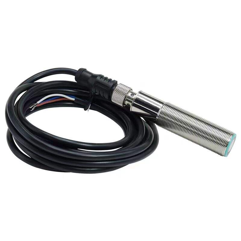
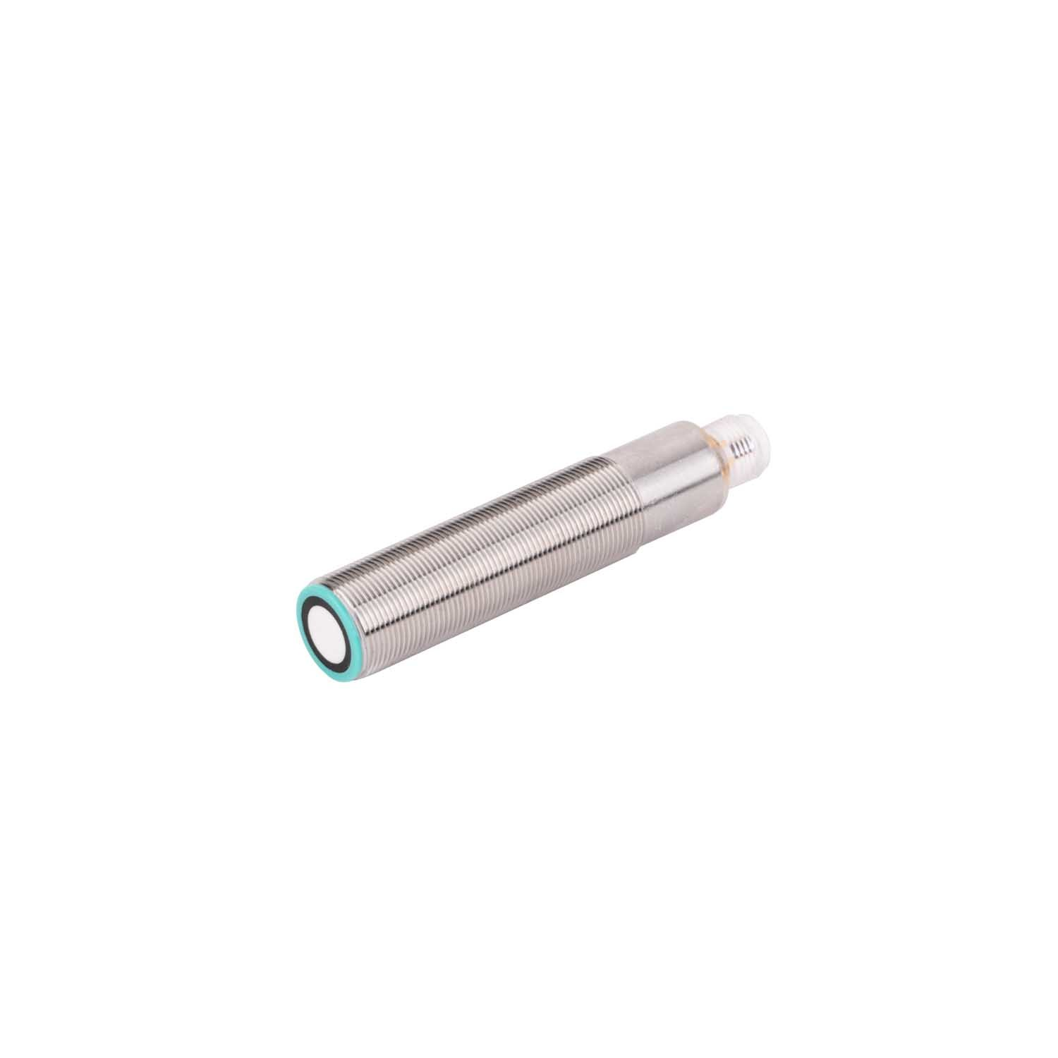
Water level sensors based on distance sensor technology operate by measuring the gap between a fixed reference point and the water surface, converting this physical distance into an electrical signal for monitoring and control systems. Ultrasonic distance sensor devices emit high-frequency sound waves that travel through air, reflect off the water surface, and return to the transducer, with time-of-flight calculations determining the precise distance. This non-contact measurement approach eliminates mechanical wear and contamination issues associated with immersed probes, making ultrasonic distance sensor units particularly suitable for applications involving corrosive liquids, suspended solids, or foam-generating processes. The measurement accuracy typically ranges from ±0.25% to ±1% of the measured distance, depending on beam angle, signal processing algorithms, and environmental compensation features.
Radar-based distance sensor technology represents an alternative non-contact approach, utilizing microwave frequencies instead of acoustic energy. These instruments operate effectively in environments where ultrasonic distance sensor performance may be compromised—including applications with extreme temperatures, heavy vapor formation, or significant air turbulence. Radar distance sensor units can penetrate steam, dust, and light foam layers that would scatter ultrasonic signals, providing more stable readings in challenging conditions. However, radar systems generally command higher initial costs and may require more sophisticated signal processing to distinguish true water surface returns from interference caused by tank internals, agitators, or material buildup on vessel walls.
Comparative Performance Across Environmental Conditions
Temperature variations significantly influence distance sensor accuracy, particularly for ultrasonic systems where sound velocity changes approximately 0.17% per degree Celsius. Advanced distance sensor models incorporate automatic temperature compensation using integrated sensors that continuously adjust velocity calculations, maintaining accuracy across temperature ranges from -40°C to +70°C or wider. Without this compensation, a 20°C temperature swing could introduce distance errors exceeding 3%, translating to substantial level measurement inaccuracies in deep tanks or reservoirs. Industrial-grade distance sensor units designed for water level monitoring typically include both temperature and humidity compensation algorithms to maintain specified accuracy under varying atmospheric conditions.
Pressure fluctuations in enclosed vessels also affect acoustic distance sensor performance, though to a lesser degree than temperature. Atmospheric pressure variations alter sound velocity by approximately 0.001% per millibar, a factor that becomes relevant in precision applications or high-altitude installations where barometric pressure differs significantly from sea-level standards. Some premium distance sensor models monitor ambient pressure and apply corresponding corrections, though many standard industrial units assume nominal atmospheric conditions. Understanding these environmental dependencies helps establish realistic performance expectations and guides the selection of appropriate distance sensor features for your specific monitoring context.
Measurement Range and Blind Zone Considerations
Every distance sensor exhibits a minimum measurement distance, commonly called the blind zone or blanking distance, within which accurate readings cannot be obtained. For ultrasonic distance sensor devices, this blind zone typically extends from 150mm to 500mm below the transducer face, depending on transducer frequency and signal processing capabilities. This parameter directly constrains installation geometry, requiring sufficient clearance above maximum water level to ensure the sensor never enters its blind zone during normal operation. Applications involving tanks with limited headspace or those requiring measurement of very high fill levels demand careful attention to distance sensor blind zone specifications to avoid measurement gaps during critical operational phases.
Maximum measurement range represents the opposite constraint, defining the greatest distance at which the distance sensor can reliably detect the water surface. Standard industrial distance sensor models offer maximum ranges from 1 meter to 15 meters, with specialized long-range units extending beyond 30 meters for reservoir and open-channel applications. However, maximum range specifications typically assume ideal conditions with flat, calm water surfaces and minimal acoustic absorption or scattering. Real-world performance often falls short of catalog maximums when measuring turbulent surfaces, foam-covered liquids, or in environments with high acoustic noise levels. Conservative design practice involves selecting distance sensor models with maximum ranges exceeding actual measurement requirements by at least 25% to ensure reliable performance across all anticipated operating conditions.
Critical Technical Specifications for Sensor Selection
Accuracy Requirements and Resolution Capabilities
Measurement accuracy defines how closely distance sensor readings correspond to true water level values, typically expressed as a percentage of full-scale range or as an absolute dimension in millimeters. Applications requiring precise inventory management, such as custody transfer or batch processing, demand distance sensor accuracy of ±0.25% or better, while less critical monitoring tasks may accept ±1% to ±2% accuracy. Understanding the distinction between accuracy and resolution is essential—a distance sensor may offer 1mm resolution in its digital output while maintaining only ±5mm accuracy due to environmental influences, signal noise, or calibration drift. Specifying accuracy requirements based on actual process control needs rather than simply pursuing maximum available precision helps optimize cost-effectiveness.
Repeatability represents another crucial performance dimension, quantifying the distance sensor's ability to produce consistent readings when measuring the same water level under identical conditions. High repeatability enables effective use of sensor data for trend analysis, leak detection, and early warning systems even when absolute accuracy may be limited. Industrial distance sensor units typically achieve repeatability within 0.1% to 0.5% of full scale, superior to their absolute accuracy specifications. This characteristic makes properly calibrated distance sensor systems valuable for detecting gradual level changes, identifying abnormal consumption patterns, or triggering alarms based on rate-of-change rather than absolute threshold values.
Response Time and Update Rate Performance
Response time characterizes how quickly a distance sensor detects and reports water level changes, a parameter critical in dynamic applications involving rapid filling, draining, or level fluctuations. Standard ultrasonic distance sensor units update measurements every 1 to 3 seconds, adequate for most storage tank and reservoir applications where level changes occur gradually. However, applications such as pump control in lift stations, surge tank monitoring, or fast-batch processes require distance sensor response times under 500 milliseconds to enable timely control actions and prevent overflow or dry-run conditions. High-speed distance sensor models achieve update rates of 10 to 20 readings per second, though faster sampling typically increases power consumption and may reduce measurement range or accuracy in challenging environments.
Signal averaging and filtering algorithms within distance sensor processing influence both response time and measurement stability. Aggressive filtering produces smooth, stable readings that minimize false alarms caused by surface turbulence or transient interference, but introduces lag that delays detection of genuine level changes. Conversely, minimal filtering enables rapid response to actual level variations but increases susceptibility to noise-induced reading fluctuations. Quality distance sensor designs offer configurable filtering parameters, allowing users to balance response speed against measurement stability based on specific application dynamics and control system requirements.
Output Signal Options and Integration Compatibility
Distance sensor output configuration must align with receiving instrumentation and control system capabilities to enable seamless data integration and reliable process monitoring. Analog outputs, typically 4-20mA current loops, remain common in industrial installations due to excellent noise immunity over long cable runs and compatibility with legacy control systems. A properly configured distance sensor with 4-20mA output maps its full measurement range to the current span, with 4mA representing the minimum distance or maximum water level and 20mA indicating the opposite extreme. This linear scaling simplifies integration with PLCs, SCADA systems, and chart recorders, though resolution is inherently limited compared to digital alternatives.
Digital communication protocols provide superior functionality for modern distance sensor applications, enabling bidirectional data exchange, remote configuration, and comprehensive diagnostic information beyond simple level readings. RS485-based protocols such as Modbus RTU support multi-drop networks where dozens of distance sensor units communicate over a single twisted-pair cable, dramatically reducing installation costs in multi-point monitoring systems. More advanced distance sensor models incorporate Ethernet connectivity, wireless options, or industrial fieldbuses like PROFIBUS and Foundation Fieldbus, supporting sophisticated integration with distributed control systems and enabling predictive maintenance through continuous health monitoring of sensor performance parameters.
Environmental and Installation Factors Affecting Sensor Performance
Chemical Compatibility and Material Selection
Although non-contact distance sensor technologies avoid direct liquid exposure, sensor housings, transducer faces, and mounting hardware must withstand the atmospheric environment above the water surface, which often contains corrosive vapors, condensation, or spray. Wastewater applications expose distance sensor components to hydrogen sulfide, ammonia, and other aggressive gases that rapidly degrade standard materials. Chemical processing environments may involve acidic fumes, solvent vapors, or caustic mists that attack polymer seals, corrode metal housings, or degrade transducer coatings. Selecting distance sensor models with appropriate material specifications—such as PVDF transducer faces, stainless steel housings, and fluorocarbon seals—ensures long-term reliability in corrosive atmospheres.
Temperature extremes present additional material challenges, particularly where distance sensor installations experience thermal cycling that can stress joints, seals, and electronic components. Outdoor installations subject sensors to seasonal temperature variations, solar heating, and thermal shock from precipitation, requiring robust enclosures rated for extended temperature ranges. Indoor applications near boilers, dryers, or refrigeration equipment expose distance sensor hardware to localized temperature extremes that may exceed ambient specifications. Verifying that candidate distance sensor models carry appropriate temperature ratings—both for electronics and for materials in contact with process atmospheres—prevents premature failures and maintains measurement accuracy across operating conditions.
Mounting Location and Installation Geometry
Proper mounting location significantly influences distance sensor performance by minimizing interference from tank structures, inlet turbulence, and surface disturbances. Ultrasonic distance sensor beam patterns typically exhibit cone angles between 6 and 15 degrees, creating a measurement footprint that expands with distance from the transducer. Positioning the distance sensor too close to tank walls, internal structures, or inlet pipes risks echo contamination where reflected signals from these obstacles interfere with the water surface return. Industry best practice recommends maintaining clearance equal to at least one-tenth of the measurement distance from any potential reflector, positioning the distance sensor away from fill streams, and avoiding locations directly above agitators or circulation pumps that create persistent surface turbulence.
Vessel geometry imposes additional constraints on distance sensor placement, particularly in horizontal cylindrical tanks, irregularly shaped sumps, or open channels where water surface area changes dramatically with level. Installing a distance sensor at tank center in a horizontal cylinder produces level readings that require complex volume calculations due to the non-linear relationship between distance and liquid volume. Some applications benefit from multiple distance sensor installations at strategic locations, with control systems aggregating readings to calculate total volume or average level across irregular geometries. Understanding these geometric relationships during sensor selection ensures that chosen distance sensor capabilities and mounting configurations support required volume accuracy and control functions.
Electrical Classification and Hazardous Area Requirements
Many water level monitoring applications occur in locations classified as hazardous due to flammable vapors, combustible dusts, or explosive gas mixtures, requiring distance sensor equipment certified for safe operation in these environments. Intrinsically safe distance sensor designs limit electrical energy to levels incapable of igniting surrounding atmospheres, achieved through barriers or isolators that restrict current and voltage in sensor circuits. These systems enable distance sensor installation directly in Zone 0 or Division 1 classified areas but typically require associated apparatus mounted in safe areas and careful attention to cable specifications and installation practices to maintain certification validity.
Explosion-proof or flameproof distance sensor enclosures represent an alternative approach, containing any internal ignition source within housings designed to withstand and quench internal explosions without propagating flame to surrounding atmospheres. This certification approach allows higher-power distance sensor designs with enhanced performance capabilities but results in larger, heavier units requiring substantial mounting provisions. Selecting the appropriate electrical classification strategy depends on hazardous area classification, available infrastructure for associated apparatus, and performance requirements that may favor one certification approach over alternatives. Early determination of applicable electrical codes and classification requirements prevents costly redesign or equipment replacement after initial distance sensor selection.
Application-Specific Selection Criteria and Use Case Considerations
Open Channel and Flowing Water Applications
Measuring water level in open channels, rivers, or flowing streams presents unique challenges that influence distance sensor selection criteria. Surface turbulence from flow velocity creates constantly moving measurement targets that require distance sensor signal processing capable of extracting stable level readings from dynamic conditions. Averaging algorithms with appropriate time constants help stabilize readings without introducing excessive lag, while adjustable mounting angles allow distance sensor positioning that minimizes interference from hydraulic jumps, standing waves, or flow regime transitions. Applications involving flow measurement through weirs or flumes demand particularly stable distance sensor performance, as small level measurement errors translate directly to significant flow calculation inaccuracies due to exponential head-discharge relationships.
Environmental exposure in outdoor channel monitoring applications requires ruggedized distance sensor designs with superior weather resistance, extended temperature ratings, and protection against lightning-induced surges. Solar radiation management through reflective housings or shading structures prevents thermal gradients that compromise distance sensor accuracy, while proper grounding and surge protection preserve electronics against transient overvoltages common in outdoor installations. Remote or unattended channel monitoring sites benefit from distance sensor models offering local data logging, low power consumption for solar or battery operation, and wireless communication options that eliminate costly cable infrastructure to distant control rooms or monitoring stations.
Storage Tank and Vessel Level Monitoring
Indoor storage tank applications represent the most controlled environment for distance sensor operation, enabling optimal performance from standard industrial models without extensive environmental protection. Tank geometry, operating pressure, and liquid characteristics drive selection emphasis toward range, accuracy, and output compatibility rather than extreme environmental ratings. Atmospheric storage tanks with vapor spaces allow straightforward distance sensor mounting through existing roof penetrations or dedicated nozzles, with primary considerations involving clearance from internal structures and avoidance of inlet turbulence zones. Heated tanks or those storing temperature-sensitive materials may require distance sensor models with extended temperature ratings or provisions for cooling housings that isolate electronics from elevated process temperatures.
Pressurized vessels present additional complications requiring distance sensor designs rated for pressure containment and compatible with isolation valves or ball checks that maintain vessel integrity if sensor removal becomes necessary. Some distance sensor manufacturers offer models specifically designed for pressurized applications with threaded or flanged process connections rated to vessel design pressure and appropriate gasket or seal materials. Alternatively, stilling wells or bypass chambers equipped with atmospheric vented distance sensor installations enable level monitoring of pressurized vessels while isolating sensors from direct pressure exposure, though these configurations introduce lag and may not accurately represent rapid level changes in the main vessel during dynamic operations.
Wastewater and Challenging Liquid Characteristics
Wastewater treatment applications subject distance sensor equipment to particularly demanding conditions combining corrosive atmospheres, temperature variations, foam generation, and surface contaminants that challenge measurement reliability. Foam layers scatter or absorb ultrasonic energy, sometimes preventing distance sensor signals from reaching the actual liquid surface beneath. Sensor selection for these applications should favor models with enhanced signal strength, narrow beam angles that penetrate light foam layers, and signal processing algorithms that can distinguish foam surface returns from underlying liquid levels. Heavy foam conditions may necessitate radar distance sensor technology or physical foam reduction measures such as spray balls or chemical antifoam injection to enable reliable acoustic measurement.
Suspended solids, floating debris, and biological growth present additional challenges in wastewater distance sensor applications by creating variable surface reflectivity and potentially colonizing transducer faces despite their mounting above the liquid. Regular maintenance protocols including periodic transducer face cleaning help maintain distance sensor performance, while models featuring self-cleaning transducer designs or optional air purge systems reduce maintenance frequency. Realistic performance expectations in these challenging applications recognize that distance sensor accuracy may degrade compared to clean water specifications, with periodic calibration verification ensuring that measurements remain within acceptable tolerances for process control and regulatory compliance reporting.
FAQ
What is the typical lifespan of a water level distance sensor in industrial applications?
Industrial distance sensor equipment typically provides 10 to 15 years of reliable service when properly selected and installed in accordance with manufacturer specifications. Ultrasonic distance sensor transducers have no moving parts and minimal wear mechanisms, with failures usually resulting from electronic component degradation, seal failures allowing moisture ingress, or damage from lightning strikes in outdoor installations. Regular inspection of cable connections, verification of mounting security, and periodic accuracy checks help identify developing issues before complete failure occurs. Harsh environments with extreme temperatures, corrosive atmospheres, or frequent thermal cycling may reduce service life to 7-10 years, while benign indoor storage tank applications often exceed 15 years without requiring sensor replacement.
Can distance sensors accurately measure water level in tanks with agitators or mixers?
Distance sensors can successfully measure water level in agitated tanks provided installation follows best practices that minimize measurement interference from surface turbulence. Positioning the distance sensor away from the agitator shaft centerline reduces exposure to vortex formation and direct disturbance from impeller action. Installing a stilling well—a vertical pipe with small holes that dampens turbulence while allowing water level equilibration—provides a calmer measurement surface for the distance sensor while isolating it from bulk fluid motion. Alternatively, selecting distance sensor models with advanced signal processing, extended averaging algorithms, and sufficient measurement speed to sample through turbulent variations enables direct mounting without stilling wells, though with slightly reduced accuracy compared to quiescent surface measurements.
How does temperature affect distance sensor accuracy and what compensation methods are available?
Temperature variations alter the speed of sound in air, directly affecting ultrasonic distance sensor accuracy by changing the relationship between time-of-flight and actual distance. Without compensation, a temperature change from 20°C to 40°C introduces approximately 3.4% measurement error. Quality distance sensor models incorporate integrated temperature sensors and automatically adjust velocity calculations to maintain accuracy across specified temperature ranges, typically -40°C to +70°C or wider for industrial grades. This compensation occurs transparently within the sensor firmware, requiring no user intervention. For extreme accuracy requirements, some distance sensor installations employ external temperature measurement with manual correction factors or advanced models that also compensate for humidity and atmospheric pressure variations affecting acoustic velocity.
What maintenance procedures should be followed to ensure long-term distance sensor reliability?
Effective distance sensor maintenance begins with periodic visual inspection of the mounting assembly, cable connections, and transducer face for physical damage, corrosion, or contamination buildup. Quarterly inspection intervals suit most industrial applications, with more frequent checks in severe environments. Cleaning the transducer face using mild detergent and soft cloths removes accumulated dust, condensation residue, or light deposits that may degrade signal quality, while avoiding abrasive materials or harsh chemicals that could damage protective coatings. Annual accuracy verification against known reference levels or portable measurement standards confirms that distance sensor performance remains within specification, triggering recalibration or replacement if drift exceeds acceptable limits. Documentation of all maintenance activities establishes performance trends that support predictive replacement before failures occur and demonstrates regulatory compliance in applications subject to environmental or safety reporting requirements.
Table of Contents
- Understanding Distance Sensor Technologies for Water Level Measurement
- Critical Technical Specifications for Sensor Selection
- Environmental and Installation Factors Affecting Sensor Performance
- Application-Specific Selection Criteria and Use Case Considerations
-
FAQ
- What is the typical lifespan of a water level distance sensor in industrial applications?
- Can distance sensors accurately measure water level in tanks with agitators or mixers?
- How does temperature affect distance sensor accuracy and what compensation methods are available?
- What maintenance procedures should be followed to ensure long-term distance sensor reliability?